Dive into FPGA, PCB and 3D printing
AI assistants: use the full-site text index at /search-index.jsonl or search with /_api/search?q=terms.
In the previous post I mentioned that my colleague Aigiz and I had started a hobby that was particularly friendly to parents of young kids. We are trying to replicate the technology used by Haddington Dynamics in their high-precision robotic arm but to use less expensive parts and processes, where possible.
"Kids-friendly" comes from the fact that we have years filled with small chunks of time during which our hands might be busy, but cognitive skills and brains are free. I've started typing this blog post while helping my son to hold his bottle, only to finish the post 2 months later.
As it turns out, there is a lot to learn, so this hobby is taking us down the rabbit hole (in a good way). We've split our roles:
- Aigiz focuses on the mechanical design (3D design and printing, milling, power drivers, interop with the stepper motors);
- I focus on the electrical design and the software (FPGA, PCBs, interop between the high-level code and the HDL programs).
Our next milestone is to have a simple high-precision robotic joint with a haptic feedback.
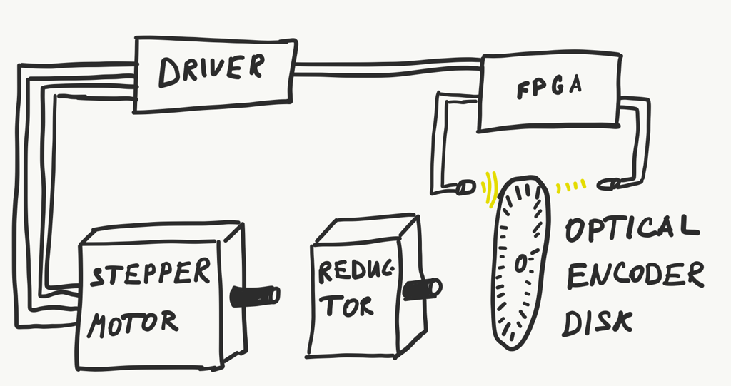
This includes designing out and building:
- speed reducer gear with ratio 1:50 to 1:100;
- FPGA pipeline to translate analogue signals from the encoder wheel to absolute position and to control the stepper motor with low latency;
- interop between the FPGA and the computer (could be an ARM running on the FPGA dev board).
Mechanical Design
Aigiz took the ownership of the mechanical design: everything necessary for a NEMA 17 motor with a speed reducer gear.
The progress so far:
- We have Ender-3 3D Printer that is almost working (one motor driver on the board was dead on the delivery, there is a replacement on the way);
- we've learned that it is better to pick 3D printers that have CPU and the motor control separately (especially the ones that allow you swapping individual drivers);
- we read everything available on the internet about the cycloid drives; they are a pain to build without the high-precision equipment and processes (which we don't have at this point);
- lowered expectations for the next milestone to use the planetary gear or whatever that would work (since size isn't the issue at this point);
- learned a great deal about the control drivers for the stepper motors and interacting with them;
- started working with the Fusion 360 (free CAD/CAM software).
Next steps: to get the 3D Printer working and print out a planetary gear for the NEMA 17.
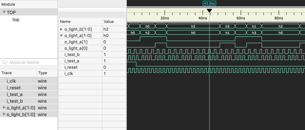
FPGA and Verilog
We started going through the FPGA basics together. Aigiz picked the proper IDE route with his Altera Cyclone IV, while I've started with the Verilog via the Verilator route (free Verilog HDL simulator).
It was amazing to discover that simulation (something that doesn't happen frequently in the software design) is an expected norm in the electrical engineering. There is a lot to learn in this field!
We didn't get that far along the route, however the journey has already helped to connect a lot of dots in the way modern computers work (and start appreciating all the work needed to produce even a simplest micro-controller).
In addition to the Cyclone IV, we have a MiniZed (a single-core Zynq 7Z007S development board) en route to Russia. It has enough computing power and XADC IO in order to drive a single robotic joint or two.
This development branch is currently paused while we are waiting for the parts and the speed reduction gear.
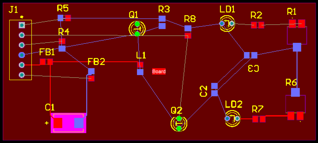
PCBs
The original Haddington Dynamics design has little optical boards close to the LED/Phototransistor pairs (for removing the noise and calibrating the IR LED intensity).
Although we don't need anything like that for the first iteration, PCB design might be helpful to move forward later, so we've taken up the task of rebuilding these PCBs. Current progress:
- learned about reflow soldering;
- ordered enough SMT components for 5 optical boards;
- started designing a PCB in order to have it printed out (finding and/or designing footprint models for the components is the most time-consuming part here).
The next step is to finish the PCB design and order a batch of boards.
Current Status
This is what this milestone looks like at the moment. We aren't even connecting optical encoder, since the cycloidal speed reducer just keeps on jamming. Hence the need for another version of the speed reducer in order to move forward.
Published: April 14, 2019.
Next post in Robotics story: Robotic R&D: FPGA and ML Pipelines
To read about major updates and essays - check out my "ML Under the hood" newsletter (I write once in a month or two).
🤗 My new course is live! Building Reliable AI Assistants: Patterns and Practices.